Advanced SolidWorks Modules: Swept, Lofted, Shell, Rib, Wrap, Pattern, Assembly, and Drawing

1. Objective

The objective of this stage is to apply and integrate advanced part modeling and assembly techniques in SolidWorks—including Swept, Lofted, Shell, Rib, Wrap, Pattern, Assembly, and Drawing tools—to design, assemble, and document a complete 3D model of a portable water purifier. This stage aims to achieve both functional precision and professional presentation under the guidance of our supervising teacher.

2. Summary of Learning

Throughout this research stage, our team explored a range of advanced modeling and assembly features in SolidWorks.

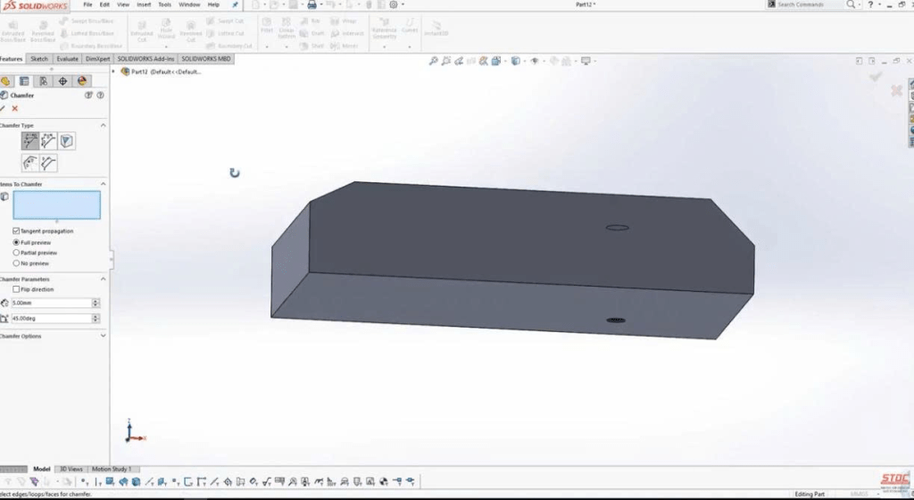
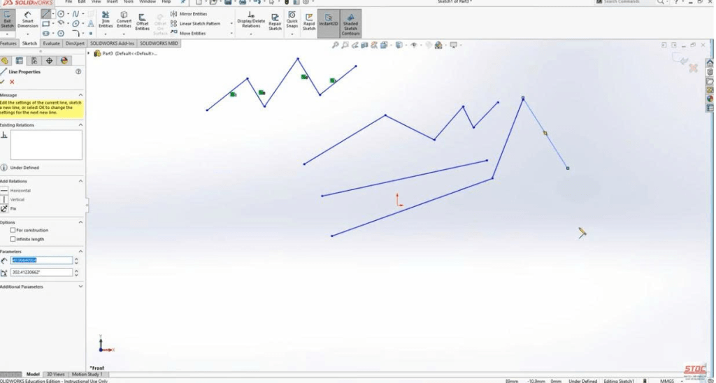
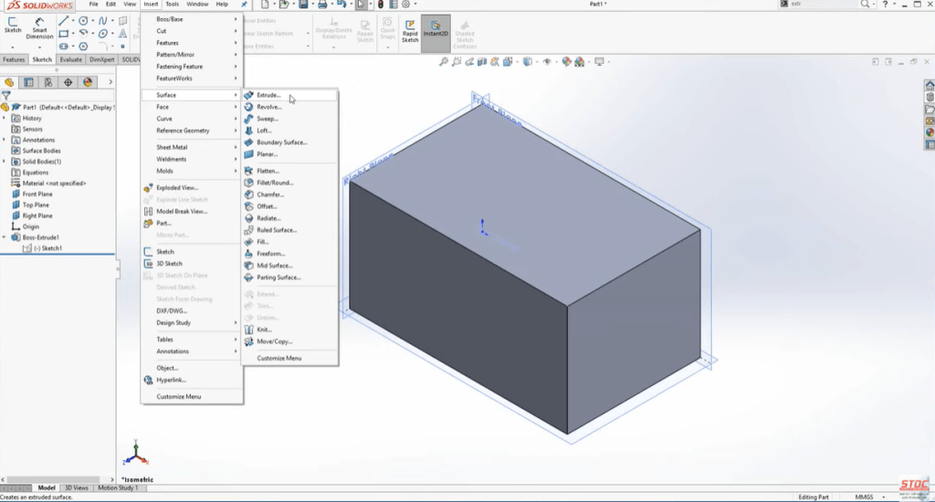
  • The Swept and Lofted commands were used to create complex geometries with smooth transitions and varying cross-sections, which are essential for designing curved connectors and streamlined fluid paths.
  • The Shell and Rib tools helped reduce material usage while maintaining structural strength, allowing us to design lightweight yet durable housings.
  • The Wrap feature was applied to project sketches onto curved surfaces, enabling the creation of engraved logos and decorative labels.
  • Pattern tools (Linear and Circular) were used to efficiently replicate repeated elements such as holes, fins, and ribs, ensuring symmetry and design consistency.

In the Assembly environment, we practiced combining all designed components using mates such as coincident, concentric, and distance to ensure precise alignment and realistic motion. Finally, in the Drawing module, our team generated 2D technical drawings from the 3D models, including dimensions, annotations, and exploded views for manufacturing documentation and presentation purposes.

3. Application to Water Purifier Design

Each advanced modeling tool was systematically applied to the portable purifier design.

  • Swept and Lofted features were utilized for internal flow tubes and filter housings.
  • Shell and Rib improved the casing’s strength-to-weight ratio and reinforced thin-walled structures.
  • Wrap added engraved labeling and aesthetic detailing, while Pattern commands allowed efficient duplication of holes, vents, and screws.

During the Assembly stage, all parts were precisely aligned and mated to form a complete prototype, ensuring smooth fit and interaction between the filters, connecting pipes, and outer frame. The Drawing environment provided professional 2D blueprints with full dimensions, annotations, and exploded views, serving as essential documentation for real-world manufacturing and assembly.

4. Conclusion

By mastering advanced modeling, assembly, and documentation tools, our team successfully created a detailed, manufacturable 3D prototype of the portable water purifier. The integration of part modeling, mechanical assembly, and engineering drawing not only enhanced technical accuracy but also reflected professional standards in product design and presentation. This stage represents a major milestone in the Eco Filter Project, demonstrating the team’s ability to move from concept to near-production readiness.

5. Next Step

The next research phase will focus on Rendering and Simulation in SolidWorks.
→ Our team will analyze fluid flow, evaluate structural strength, and create realistic visual renderings of the water purifier to assess both functional performance and presentation quality before prototype fabrication.

Research Note: Advanced Sketch Editing and Feature Application in SolidWorks

1. Objective

The objective of this stage is to apply advanced sketch editing, constraint, and feature tools in SolidWorks to design and refine the structural components of a portable water purifier. This process ensures precision, functionality, and manufacturability in the 3D model under the supervision of our instructor.

2. Summary of Learning

In this research session, our team explored advanced sketching and feature tools in SolidWorks. We practiced using Trim Entities, Extend Entities, and Offset Entities to edit and adjust sketches efficiently. In addition, we applied Geometric Relations such as Parallel, Perpendicular, Tangent, and Equal to fully constrain sketches and maintain dimensional accuracy after modifications.

We then learned to use the Extrude Cut feature to remove material from solid models, creating holes, slots, and internal cavities—essential elements for pipe connectors and filter housings in the purifier. Important precautions were emphasized, including selecting the correct sketch plane, verifying cut direction, and avoiding undesired intersections between components.

Furthermore, we studied key Feature Tools such as Hole Wizard, Chamfer, and Fillet. The Hole Wizard enabled the creation of standardized screw holes for consistent assembly alignment, while Chamfer and Fillet enhanced both functionality and aesthetics by removing sharp edges and improving surface transitions.

3. Application to Water Purifier Design

These tools were directly applied to the development of the purifier’s main structure. Advanced sketch editing and constraint commands helped refine the designs of the connecting pipes and filter holders, ensuring geometric precision. The Extrude Cut tool was used to create internal flow passages and openings, while the Hole Wizard provided accurate placements for screws used in frame assembly.
Additionally, Chamfer and Fillet features were implemented to improve mechanical durability, user safety, and maintenance convenience by eliminating sharp or fragile edges.

4. Conclusion

Mastering advanced sketching and feature tools in SolidWorks is essential for producing accurate, manufacturable, and realistic 3D components. Through this stage, our team strengthened its technical ability to translate design intent into functional solid models. These skills form the foundation for prototype fabrication and ensure that all parts meet the structural and functional standards required for the Eco Filter Project.

5. Next Step

Our next phase will focus on Assembly Tools in SolidWorks, where all designed parts will be integrated into a complete 3D assembly for mechanical testing, motion simulation, and visualization of the final portable water purifier.

Research Note – Application of Basic Sketching Commands in SolidWorks for Water Purifier Design

1. Objective

The objective of this stage is to apply fundamental sketching techniques in SolidWorks to design the structural components of a portable water purifier. This step marks the transition from basic interface familiarity to practical design application, carried out under the supervision of our instructor.

2. Summary of Learning

In this research phase, our team learned to create precise 2D sketches using the Basic Sketching Commands in SolidWorks. We began by selecting appropriate sketch planes—Front, Top, or Right—and utilized essential tools such as Line, Rectangle, Circle, and Arc to define basic geometries.
We then applied Smart Dimensions to specify exact measurements and Geometric Relationships (Parallel, Perpendicular, Tangent) to ensure that the sketches were fully constrained and geometrically stable.

Additional functions like Trim Entities, Offset Entities, and Mirror Entities were used to refine and optimize sketch structures. For instance, the Trim command allowed us to remove unnecessary segments, while the Mirror tool enabled the efficient creation of symmetrical shapes. Color indicators in SolidWorks (blue – under-defined, black – fully defined, red – over-defined) provided real-time feedback on sketch accuracy and definition.

3. Application to Water Purifier Design

These sketching techniques were directly applied to define the 2D profiles of key components, including the filter housing, connecting pipes, and base frame of the portable purifier. Accurate sketching ensured that each component would align properly during the 3D assembly stage and meet the mechanical and functional requirements of the purifier.
By consistently using geometric constraints and precise dimensions, our team established a uniform design standard, ensuring structural consistency across multiple parts before extrusion into 3D models.

4. Conclusion

This stage strengthened our team’s ability to develop accurate and well-constrained 2D sketches in SolidWorks. Mastering these basic sketching commands forms the foundation for creating detailed 3D models in subsequent phases. The skills gained in this step are essential for ensuring dimensional accuracy, geometric stability, and overall compatibility among components in the Eco Filter Project.

5. Next Step

In the next research stage, our team will proceed to Lesson 3: “Creating 3D Features in SolidWorks.”
→ The upcoming tasks will involve extruding and revolving sketches to generate solid models of the purifier’s main body, housing, and handle components.

Eco Filter Project


Research Note – Initial Phase: Learning SolidWorks Interface for Portable Water Purifier Design

1. Objective

The objective of this stage is to familiarize our research team with the SolidWorks interface and its fundamental operations in preparation for the 3D design of a portable water purifier. Understanding the software environment is essential for developing accurate models of mechanical components during later design phases under the supervision of our instructor.

2. Background

SolidWorks is a professional CAD (Computer-Aided Design) software widely used in mechanical engineering and product development. Since this research involves designing and simulating the mechanical parts of a water purification system, it is crucial for our team to master the software’s basic functions—such as interface navigation, workspace configuration, and model manipulation. Acquiring these skills ensures accuracy and consistency throughout the entire design and development process.

3. Summary of Learning

Our team completed the lesson “Basic Interface and Operations in SolidWorks 2017–2022.”
During this stage, we learned to identify and utilize key interface elements:

  • Menu Bar: provides access to file and system functions.
  • Command Manager: contains essential modeling tools.
  • Feature Manager Design Tree: organizes model features and hierarchy.
  • Graphics Area: allows 3D visualization, rotation, zooming, and panning of objects.

We also practiced customizing the workspace by adjusting units from inches to millimeters and hiding unnecessary toolbars to create a cleaner and more efficient environment. These operations are fundamental for smooth modeling in the following stages of the project.

4. Application to Research

The knowledge gained in this phase will be applied to the design of critical components of the portable water purifier, including:

  • The outer housing that contains the filter and water chamber,
  • Connector joints that manage water inflow and outflow, and
  • The filter compartment that stores purification materials.

By gaining a solid understanding of the SolidWorks interface, our team can create precise sketches and assemblies, ensuring both mechanical functionality and portability in the final prototype. This stage also laid the groundwork for efficient collaboration during the 3D modeling process.

5. Conclusion

This initial research stage successfully established a technical foundation for 3D modeling in SolidWorks. Under the guidance of our supervising teacher, our team developed confidence in navigating the software and performing essential operations. These skills will support subsequent stages of the Eco Filter Project, where mechanical parts will be modeled and assembled into a complete system.

6 .Next Step:
Proceed to Lesson 2 — “Basic Sketching Commands in SolidWorks”
→ Begin creating 2D sketches for the filter housing and handle structure of the portable purifier.